
Abstract
The NAC 72, was introduced in the early 1990s, as a succesor to the almighty NAC 32. It is the first Naim preamp that featured the "Time Aligned" input buffer, and the last Naim preamp to feature a mechanical input selector.
The NAC 72 was originally designed to be powered by a hicap, i.e. two rails of 24v. This article explains how to modify the NAC 72, to accept a DualTeddyCap, i.e. 4 rails of 24v, in the same fashion as the more expensive NAC 82.
Disclaimer
1. The modifications described in this article require advanced soldering skills. If you are not fully confident with the soldering iron, do not attempt these on your own, and hand it to a skilled technician.
2. These modifications are fully reversible, just recover the original wiring back.
3. Disconnect the preamplifier from all power supplies and connected equipment before opening it.
About DualTeddyCap
The DualTeddyCap (DTC) features two seperate TeddyCap's, each one with its own transformer secondary, Tedinator discrete regulator and output stage.
The DTC can power two Naim devices (e.g. Naim Nait XS and Stageline), or deliver two upgrade ports for Naim NAC 82 and NAC 282.
Step 1: Connectors
Originally, the NAC 72 (as well as NAC 32.5) features two power entry sockets:
1. DIN 5pin 240 degrees - for connecting Hicap/TeddyCap.
2. DIN 4pin 270 degrees - for connecting power amp directly (e.g. NAP 140/180 etc).
1. We will keep the original DIN 5pin socket, or replace it with a new one if it oxidized.
2. We will replace the DIN 4pin with a new DIN 5 pin 240 degrees. It is available from several suppliers, part number: Prehkeytec 71206-050/0800.
DIN Socket wiring
Wiring the two DIN connectors is easy, as long as you follow the typical Naim wiring scheme.
We will assign the power rails with numbers, as following:
1. New DIN connector - pins 1,5 accept 24v power rails - connect two wires about 25cm long, we will mark them with "1" and "2" . Pin3 is ground - use the same ground wire that originally connected the DIN 4 socket..
2. Original DIN 5pin connector - we will keep it in original form - no need to change anything. Its power rails are already connected to the board, those will be assigned "3" and "4".
Card Removal
In a typical configuration, a NAC 72 will includes several boards. The following are considered minimal configuration:
1. NA 729 - time aligned buffer (in NAC 32 - NA 324 buffers).
2. NA 321 - gain boards
3. Relay board.
Additional boards are optional, and should be removed if not used:
4. NA 324 tape buffer boards - use them only if you are connecting headphone amplifier or a tape recorder.
5. NA 322/323 phono boards - use them only if you plan to connect a turntable without an external phonostage.
6. NA 328 variable boards - these allow input level attenuation - we prefer to remove them altogether, and just reduce the final gain of the 321 boards.
Power Distribution Strategy
We usually prefer the following distribution rules:
1. Left and right channels are always connect to separate power feeds. Therefore every pair of boards receive a pair of power feeds.
2. NA 321 - these are the gain boards, thus require a dedicated power source - we will connect them to rails 1,2.
3. The rest of the boards - NA 729, NA 323 and relay board - those will be powered by rails 3,4.
4. We will need to make incisions to the power traces, the goal is to minimize the number of incisions. Therefore The relay will stay with rail 4 (original trace), same applies for the phono and buffer boards, keeping in mind rule #1.
Preparing the main board
The modification requires four PCB trace cuts and four additional power wires.
Start by remove all plug-in boards, disconnect the front-panel illumination wiring and release the front-panel switches and potentiometers as required.
Remove the main board from the chassis, take detailed photographs before disconnecting any wiring.
Label all wires and connectors.Once the main board has been removed, identify and verify every trace that is to be cut before making any incision.
Incisions and wiring
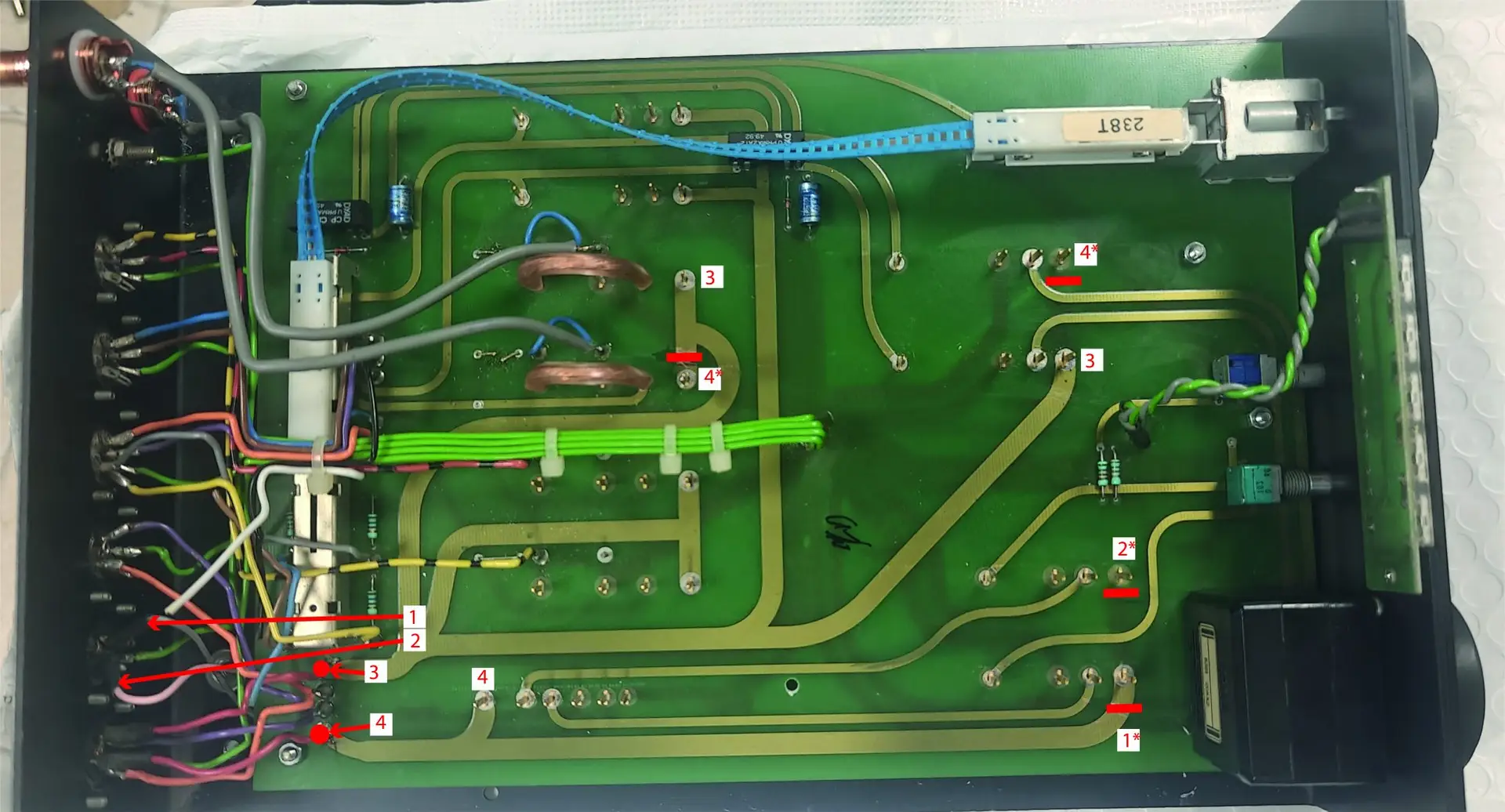
The mod requires making 4 incisions, and running 4 wires directly to the power entry pins of the different boards - either for the DIN socket (numbers 1,2) or from the power entry pins (marked 3,4). All 4 wires should run underneath the board.
The diagram below explains the rail numbers and the 4 trace cuts (marked in red) - either on the top or bottom side of the board.
The power pins that require running dedicated wires are marked with (*)
Further modifications - the "good-old 27R-47uF"
A lot has been said about the RC damping filter that is found in every Naim preamp circuit since the early days. This arrangement may have been required back in the days of the original Hicap, due to the use of LM317 regulators.
When using TeddyCap or DualTeddyCap, the damping circuit brings no significant benefits, therefore we recommend the replace the 27 Ohm resistor with a low value - a 1 Ohm would be just fine.
